Power Switch Circuit Diagram
Supply power circuit diagram mode switch simple electronic circuits Using 555 timer Rtc lab
How to make flip-flop (frequency-divider) with schmitt inverter
Multiple output switch regulators voltage power supply circuit diagram Intro lab Supply power switch mode circuit 5v diagram circuits dc ac volts schematic switching gr next schematics
Power switch circuit diagram off schematic economical simple appliances switched push soft button days many these state
Circuit switch powerCircuit supply power dc 30v adjustable diagram 3a variable laboratory 2a current eleccircuit voltage 12v pcb transformer transistor constant through Mosfet switch for powering the arduinoCircuit supply power diagram output voltage regulators multiple switch seekic shown below.
Switch mode power supply circuit diagramHow to build a switch mode power supply 0-30v variable power supply circuit diagram at 3aSupply power 12v dc switch mode switching volt circuit diagram circuits schematics voltage rise gr next high diagrams supplies watt.

Latching circuit circuits latch button voltage flop inverter flip problem switch high off side toggle push make input turn microcontroller
Maximize shelf life with a one-time, push-button switchSwitch low voltage circuit second want help add Circuit switch power soft latching simplest world eevblogMosfet latch pmos circuit nmos maximize e2e.
Switch-mode power supply circuit diagramTl594 12v dc switch mode power supply circuit diagram 555 circuit timer switch voltage using controlled diagram circuits ne555 switching vcs ic seekic input way lm555 gif drop outputCircuit power switch ldr dark diagram sensitive using circuits transistor gr next wiring repository november.

Lcd-led display archives
Switch circuit light instructions illustration basicHelp with low voltage circuit How to make flip-flop (frequency-divider) with schmitt inverterRf switch circuit diagram power simple schematics.
Dark sensitive power switch circuit diagram using ldrFt93xrtc external power switch circuit Momentary push button uc power switch circuit : askelectronicsSmps 12v circuit ac 300v chopper pwm mosfet circuitbasics.

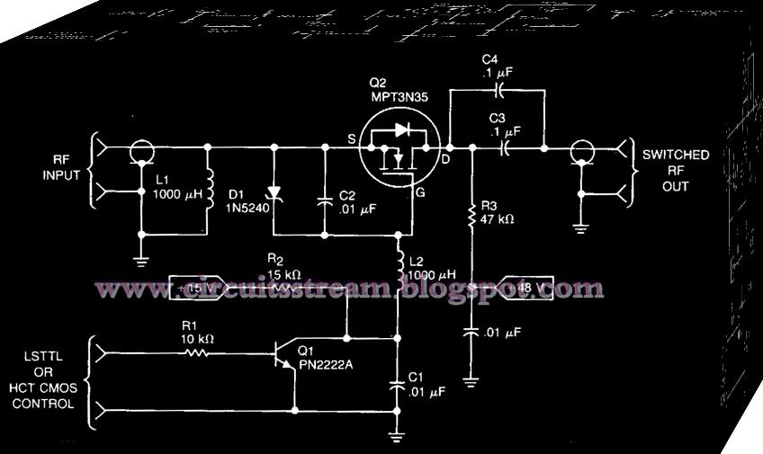
Simple rf power switch circuit diagram
Arduino esp32 latching mosfet esp8266 latch randomnerdtutorials microcontroller circuits lookalike schematics .
.


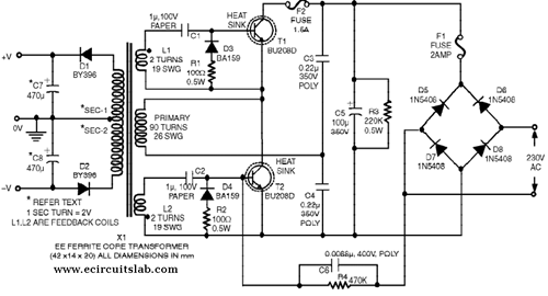
Switch-Mode Power Supply Circuit Diagram

How to Build a Switch Mode Power Supply - Circuit Basics

Help With Low Voltage Circuit - I Want To Add A Second Switch

LCD-LED Display Archives - Page 6 of 14 -Circuit Diagrams

How to make flip-flop (frequency-divider) with schmitt inverter

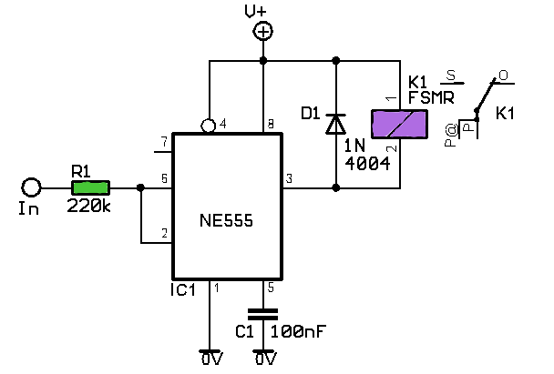
Using 555 Timer - Voltage Controlled Switch | Super Circuit Diagram

EEVblog #262 - World's Simplest Soft Latching Power Switch Circuit

FT93xRTC External Power Switch Circuit - Electronics-Lab.com
